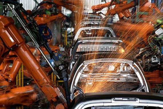
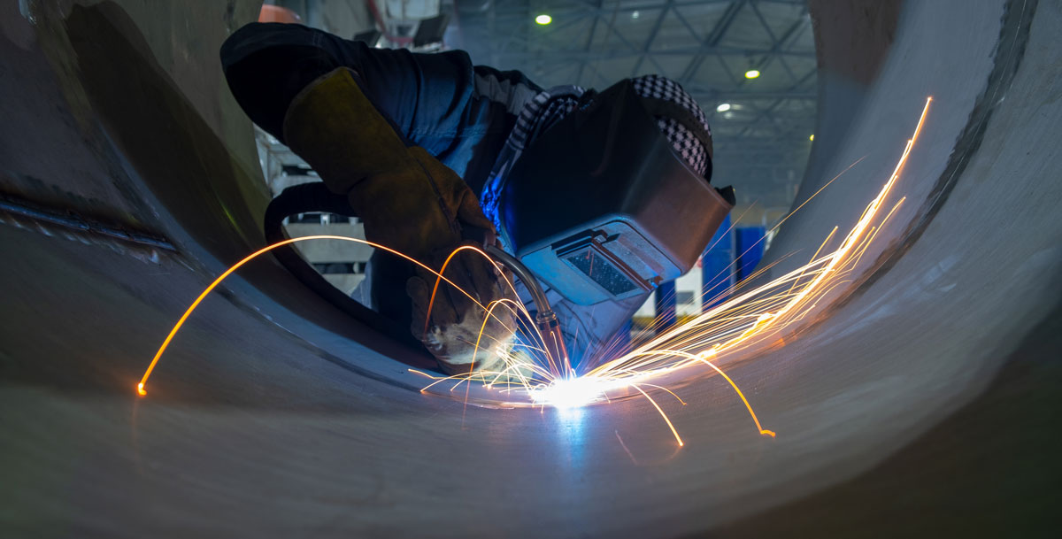
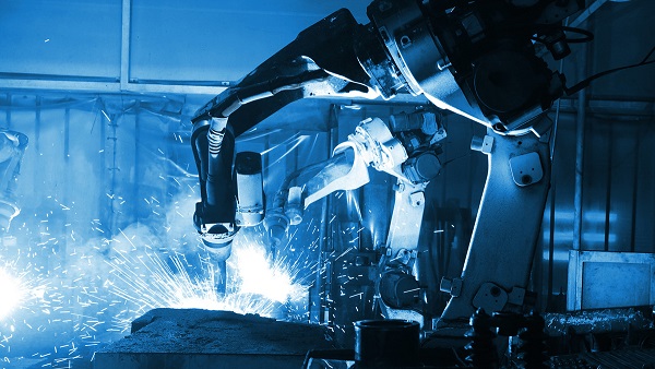
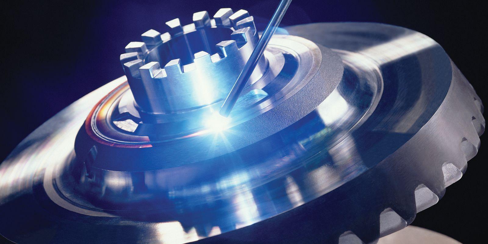
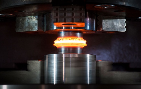
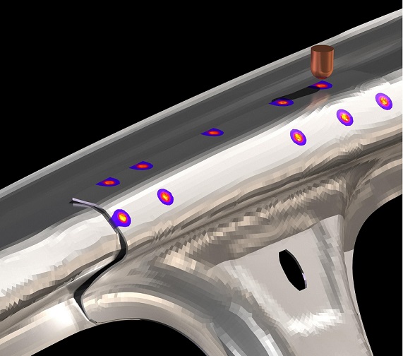
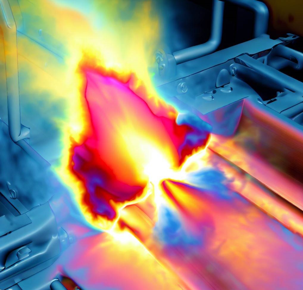
Simulation Dynamics engineers simulate the Welding with innovative CAE and virtual prototyping available in the non-linear structural codes such as LS-DYNA, Ansys and ABAQUS. The Finite element analysis of welding include Arc Welding, laser Beam Welding, RSW, FSW and transfer the results of welding simulation for next simulation like NVH, Crash test, Tension, Compression and shear test and fatigue simulation.
Contact US and Discover SolutionsArc welding processes, such as SMAW, GMAW (MIG), GTAW (TIG), SAW, and others, are widely used in various industries due to their flexibility, high productivity, and relatively low equipment costs. These processes involve the use of an electric arc that melts and fuses the workpiece materials, creating a strong joint.
SMAW (Shielded Metal Arc Welding), also known as stick welding, is commonly used for welding steel and stainless steel in construction, repair, and maintenance applications. The process uses a consumable electrode coated with flux, which produces a protective gas shield to protect the weld from atmospheric contamination.
GMAW (Gas Metal Arc Welding), also known as MIG (Metal Inert Gas) welding, is a popular welding process for mild steel, stainless steel, and aluminum. It uses a wire electrode that is continuously fed into the weld pool, along with a shielding gas that protects the weld from atmospheric contamination.
GTAW (Gas Tungsten Arc Welding), also known as TIG (Tungsten Inert Gas) welding, is commonly used for welding thin materials such as aluminum and stainless steel. It uses a non-consumable tungsten electrode and a shielding gas to protect the weld from atmospheric contamination.
SAW (Submerged Arc Welding) is a high-productivity welding process commonly used in heavy fabrication and manufacturing industries, such as shipbuilding, construction, and pressure vessel manufacturing. The process involves feeding a consumable electrode into a molten pool, which is submerged under a layer of flux that protects the weld from atmospheric contamination.
Other arc welding processes, such as plasma arc welding, atomic hydrogen welding, and carbon arc welding, are also used in specialized applications.
Revolutionize Fluid Dynamics with CFD Simulation.
Brazing is a thermal joining process that uses a melted filler material to connect metal components. The filler material typically has a lower melting point than the components being joined, and it is used to fill the gap between the two components. Brazing is often used in applications where a strong, durable joint is required, such as in the aerospace, automotive, and manufacturing industries.
One of the main advantages of brazing is its relatively low heat input, which can help prevent distortion and damage to the components being joined. This makes it a useful process for joining dissimilar metals and for joining components that are sensitive to high heat. Brazing can also produce joints of considerable strength and durability, making it a popular choice for applications where reliability and longevity are important.
Simulation Dynamics engineers use innovative CAE (Computer-Aided Engineering) and virtual prototyping techniques to simulate the brazing process. These techniques allow them to analyze the behavior of the joint and predict its performance under various conditions. Non-linear structural codes such as LS-DYNA, Ansys, Comsol, Simufact Welding, and ABAQUS are commonly used to simulate the brazing process and optimize the design of the joint.
Engineering Reliability, One Simulation at a Time.
Laser beam welding is a process that uses a high-energy laser beam to heat and weld metal components together. The laser beam is directed at the joint between the components, melting the metal and creating a strong, precise bond. One of the advantages of laser beam welding is its relatively narrow heat-affected zone, which helps minimize distortion and damage to the surrounding material. This makes it a popular choice for welding thin materials, such as those used in the aerospace and medical industries.
Electron beam welding is a similar process that uses a high-energy beam of electrons to melt and weld metal components together. The electron beam is focused onto the joint between the components, creating a high-intensity heat source that melts the metal and creates a strong, precise bond. Like laser beam welding, electron beam welding can produce precise welds with a narrow heat-affected zone. It is often used in high-tech applications such as the aerospace and semiconductor industries.
Both laser beam welding and electron beam welding offer several advantages over other welding processes. They are both highly precise, and their narrow heat-affected zones help prevent distortion and damage to surrounding materials. However, both processes require specialized equipment and expertise, which can make them more expensive and difficult to use than other welding methods.
Artificial Intelligence & Machine Learning Powers the Future of Simulation.
Pressure welding is a group of joining processes that use heat and pressure to join components together. These processes can be categorized into two main groups: resistance welding and friction welding.
Resistance welding involves passing an electrical current through the components being joined, which generates heat at the interface and melts the materials together. The two most common types of resistance welding are spot welding and seam welding. In spot welding, a small area of the components is heated and fused together, while in seam welding, a continuous seam is created along the length of the components.
Friction welding involves rubbing two components together at high speed to generate heat, which melts the materials and creates a bond between them. The two most common types of friction welding are rotary friction welding and linear friction welding. In rotary friction welding, one component is rotated against another component until they heat up and bond together. In linear friction welding, the components are moved back and forth against each other until they bond together.
AI Transforms Multiphysics Simulation.
Resistance Spot Welding (RSW) is a pressure welding process used to join two metal sheets together. In RSW, copper electrode welding guns are used to press the sheets together, while an electrical current is passed through them. The heat generated by the electrical current melts the sheets together, creating a small circular welded area between them.
The RSW process is commonly used in the automotive industry for welding body panels and other sheet metal components. It offers several advantages over other welding processes, including high speed, low cost, and the ability to produce consistent, high-quality welds.
To simulate the RSW process, engineers use computer-aided engineering (CAE) software to model the electrical, thermal, metallurgical, and mechanical behavior of the joint. The software calculates the heat generated by Joule's heating, which is the heating effect caused by the electrical current passing through the metal.
The standard approach in an RSW model involves fully coupled electrical, thermal, metallurgical, and mechanical steps. This means that the software takes into account the electrical resistance, thermal conductivity, melting, and solidification of the metal, as well as the mechanical forces involved in the welding process.
By simulating the RSW process, our engineers can optimize the design of the joint and identify potential issues before the welding takes place. This helps ensure that the joint will meet the required specifications and perform reliably in the intended application.
Generative Design + CFD: Topology-Optimized Fluid Dynamics
Stress relieving is a heat treatment process that is commonly used after welding to reduce residual stresses in the assembly. The process involves heating the metal to a specific temperature and holding it there for a certain amount of time, followed by controlled cooling.
The Stress Relief Heat Treatment process includes the definition of time-temperature curves for the heating, holding, and cooling phases. The curves are designed to ensure that the metal is heated and cooled at a rate that will reduce residual stresses without causing any additional distortion or cracking.
FEA Stress relief simulation is conducted taking into account two mechanisms: Stress relaxation due to decreased yield stress of the material during heating and time-dependent creep properties of the material. The simulation calculates the temperature distribution, thermal gradients, and residual stresses in the welded assembly after the stress relieving heat treatment process.
The main goal of stress relieving is to improve the overall structural integrity of the assembly. Residual stresses can cause distortion, warping, and cracking in the metal, leading to premature failure. By reducing these stresses through stress relieving, the assembly can perform more reliably and have a longer service life.
Cognitive FEA: Machine Learning-Predictive Structural Integrity